Harley ProSwitch/AM IIIGPI Control Interface Connection Method
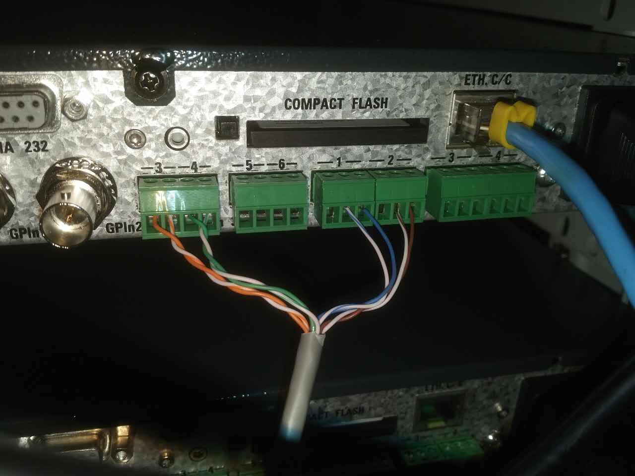
GPI Panel Connection with ProSwitch/AM III
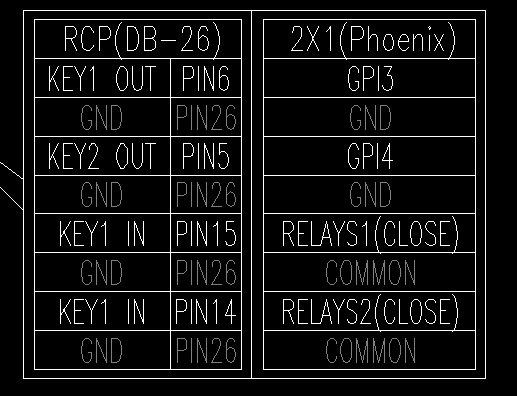
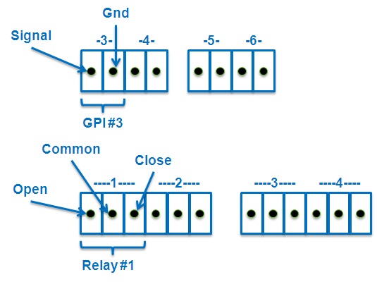
(Connect COMMON and CLOSE pins on the RELAYS!)
ProSwitch/AMIII Settings:
Web Settings:
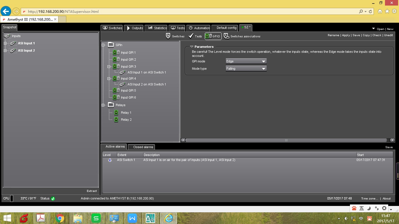
Set GPI 3 to Edge—specifically, edge-triggered, and configure the mode to: falling—meaning falling edge triggered. At the same time, set the control group to Switch for ASI output1.
Set GPI 4 to Edge—specifically edge-triggered, and configure the mode to: falling—meaning falling edge triggered. At the same time, set the control group to Switch for ASI output2.
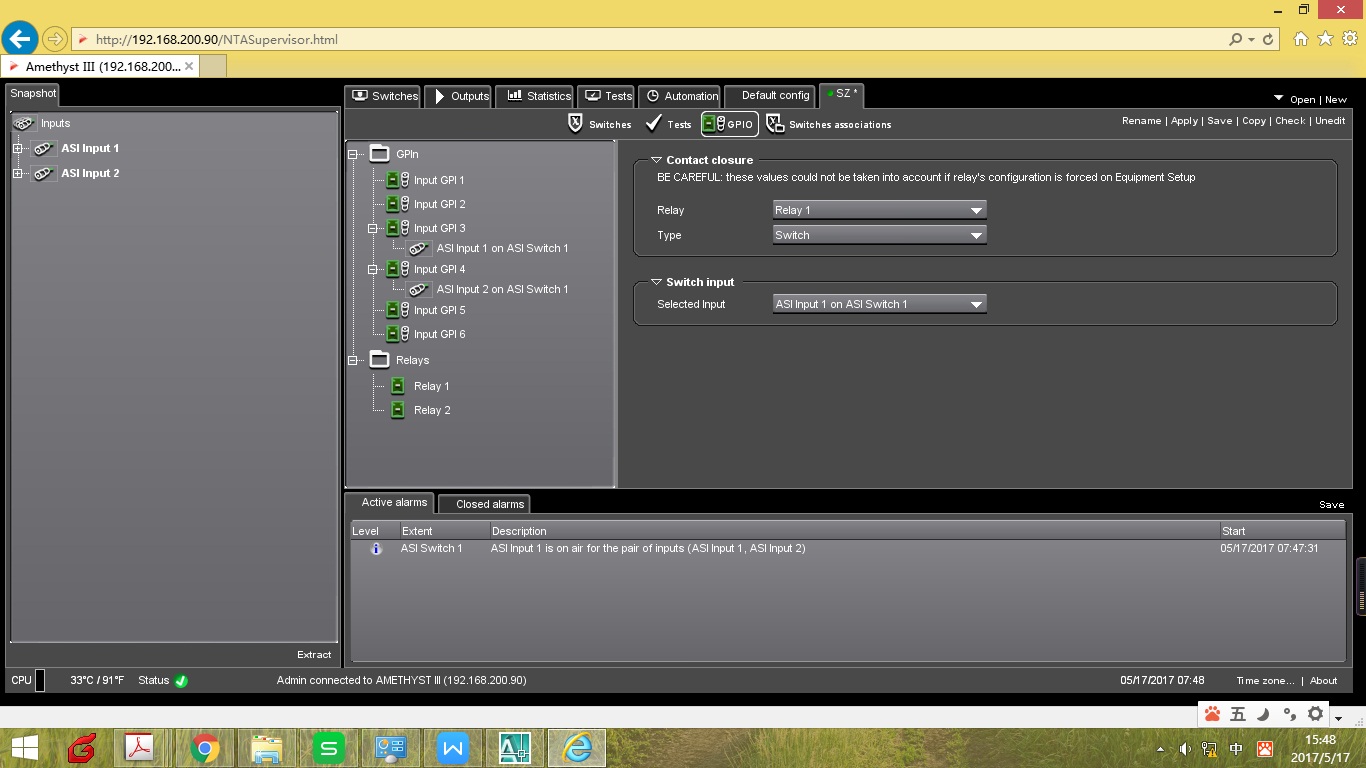
Set RELAYS1 to Edge—meaning edge-triggered, and set the mode to: Switch—meaning falling edge triggered. At the same time, set the control group to Switch for ASI output1.
Set RELAYS2 to Edge—meaning edge-triggered, and set the mode to: Switch—meaning falling edge triggered. At the same time, set the control group to Switch for ASI output2.
Local Settings:
Change all RELAYS1-3 to In Configuration. (A device restart is required after making changes!)
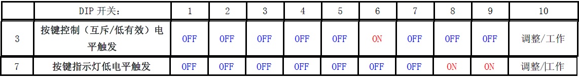
Panel Settings: